Product Description
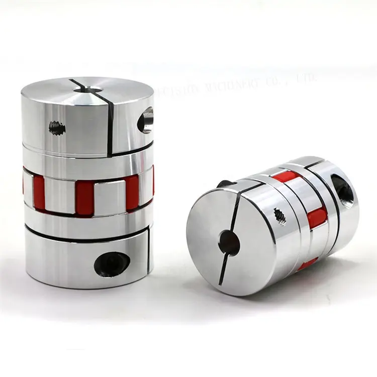
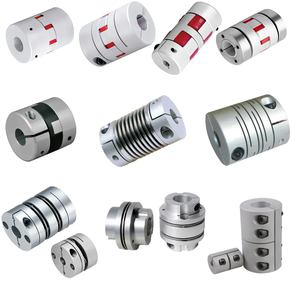
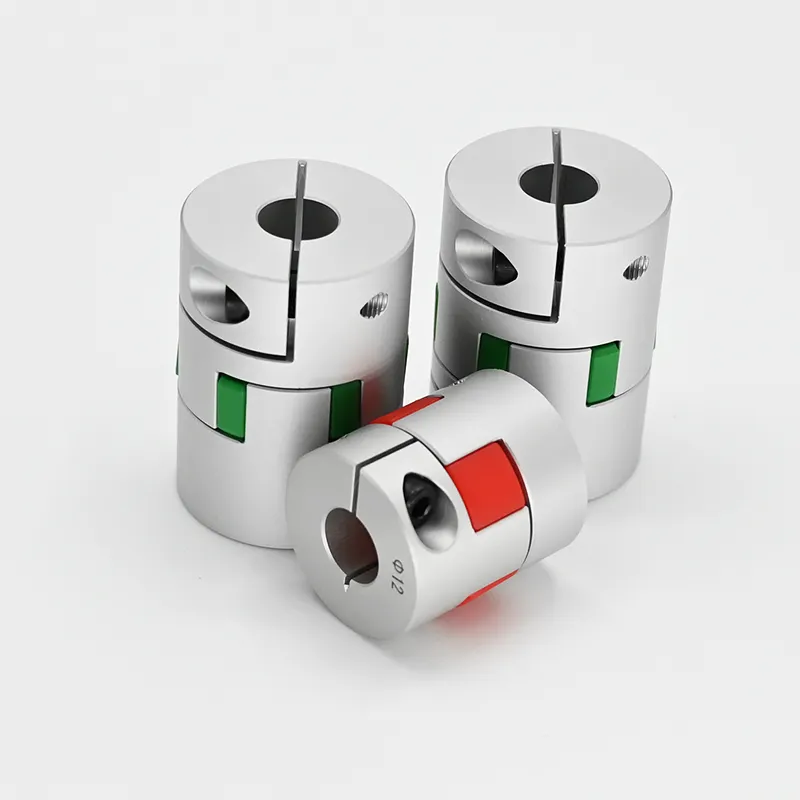
GFC-80X114 Manufacturer Flexible Clamp Style GFC Shaft Spider Gear Motor Jaw Coupling
GFC-80X114 Manufacturer Flexible Clamp Style GFC Shaft Spider Gear Motor Jaw Coupling
| model parameter | common bore diameter d1,d2 | ΦD | L | LF | LP | F | M | tightening screw torque (N.M) |
| GFC-14X22 | 3,4,5,6,6.35 | 14 | 22 | 14.3 | 6.6 | 5.0 | M2.5 | 1.0 |
| GFC-20×25 | 3,4,5,6,6.35,7,8,9,9.525,10 | 20 | 25 | 16.7 | 8.6 | 5.9 | M3 | 1.5 |
| GFC-20X30 | 3,4,5,6,6.35,7,8,9,9.525,10 | 20 | 30 | 19.25 | 8.6 | 5.9 | M3 | 1.5 |
| GFC-25X30 | 4,5,6,6.35,7,8,9,9.525,10,11,12 | 25 | 30 | 20.82 | 11.6 | 8.5 | M4 | 2.5 |
| GFC-25X34 | 4,5,6,6.35,7,8,9,9.525,10,11,12 | 25 | 34 | 22.82 | 11.6 | 8.5 | M4 | 2.5 |
| GFC-30×35 | 5,6,6.35,7,8,9,10,11,12,12.7,14,15,16 | 30 | 35 | 23 | 11.5 | 10 | M4 | 2.5 |
| GFC-30X40 | 5,6,6.35,7,8,9,10,11,12,12.7,14,15,16 | 30 | 40 | 25 | 11.5 | 10 | M4 | 2.5 |
| GFC-40X50 | 6,8,9,10,11,12,12.7,14,15,16,17,18,19,20,22,24 | 40 | 50 | 32.1 | 14.5 | 14 | M5 | 7 |
| GFC-40X55 | 6,8,9,10,11,12,12.7,14,15,16,17,18,19,20,22,24 | 40 | 55 | 34.5 | 14.5 | 14 | M5 | 7 |
| GFC-40X66 | 6,8,910,11,12,12.7,14,15,16,17,18,19,20,22,24 | 40 | 66 | 40 | 14.5 | 14 | M5 | 7 |
| GFC-55X49 | 10,11,12,12.7,14,15,16,17,18,19,20,22,24,25,28,30,32 | 55 | 49 | 32 | 16.1 | 13.5 | M6 | 12 |
| GFC-55X78 | 8,10,12,12.7,14,15,16,17,18,19,20,22,24,25,28,30,32 | 55 | 78 | 46.4 | 16.1 | 19 | M6 | 12 |
| GFC-65X80 | 14,15,16,17,18,19,20,22,24,25,28,30,32,35,38,40 | 65 | 80 | 48.5 | 17.3 | 14 | M8 | 20 |
| GFC-65X90 | 14,15,16,17,18,19,20,22,24,25,28,30,32,35,38,40 | 65 | 90 | 53.5 | 17.3 | 22.5 | M8 | 20 |
| GFC-80X114 | 19,20,22,24,25,28,30,32,35,38,40,42,45 | 80 | 114 | 68 | 22.5 | 16 | M8 | 20 |
| GFC-95X126 | 19,20,22,24,25,28,30,32,35,38,40,42,45,50,55 | 95 | 126 | 74.5 | 24 | 18 | M10 | 30 |
| model parameter | Rated torque (N.M)* |
allowable eccentricity (mm)* |
allowable deflection angle (°)* |
allowable axial deviation (mm)* |
maximum speed rpm |
static torsional stiffness (N.M/rad) |
moment of inertia (Kg.M2) |
Material of shaft sleeve | Material of shrapnel | surface treatment | weight (g) |
| GFC-14X22 | 5.0 | 0.1 | 1 | ±02 | 10000 | 50 | 1.0×10⁻⁶ | High strength aluminum alloy | Polyurethane imported from Germany | Anodizing treatment | 10 |
| GFC-20X25 | 5.0 | 0.1 | 1 | ±02 | 10000 | 50 | 1.0×10⁻⁶ | 15 | |||
| GFC-20X30 | 5.0 | 0.1 | 1 | ^02 | 10000 | 53 | 1.1×10⁻⁶ | 19 | |||
| GFC-25X30 | 10 | 0.1 | 1 | 10000 | 90 | 5.2X10⁻⁶ | 33 | ||||
| GFC-25X34 | 10 | 0.1 | 1 | £)2 | 10000 | 90 | 5.2×10⁻⁶ | 42 | |||
| GFC-30X35 | 12.5 | 0.1 | 1 | ±02 | 10000 | 123 | 6.2×10⁻⁶ | 50 | |||
| GFC-30×40 | 12.5 | 0.1 | 1 | 102 | 10000 | 123 | 6.2×10⁻⁶ | 60 | |||
| GFC-40X50 | 17 | 0.1 | 1 | 8000 | 1100 | 3.8×10⁻⁵ | 115 | ||||
| GFC-40X55 | 17 | 0.1 | 1 | ±02 | 8000 | 1100 | 3.8×10⁻⁵ | 127 | |||
| GFC-40X66 | 17 | 0.1 | 1 | 7000 | 1140 | 3.9×10⁻⁵ | 154 | ||||
| GFC-55X49 | 45 | 0.1 | 1 | ±02 | 6500 | 2350 | 1.6×10⁻³ | 241 | |||
| GFC-55X78 | 45 | 0.1 | 1 | 102 | 6000 | 2500 | 1.6×10⁻³ | 341 | |||
| GFC-65X80 | 108 | 0.1 | 1 | ±02 | 5500 | 4500 | 3.8×10⁻³ | 433 | |||
| GFC-65X90 | 108 | 0.1 | 1 | ±02 | 5500 | 4800 | 3.8×10⁻³ | 583 | |||
| GFC-80X114 | 145 | 0.1 | 1 | £)2 | 4500 | 5000 | 1.8×10⁻³ | 1650 | |||
| GFC-95X126 | 250 | 0.1 | 1 | ±02 | 4000 | 5000 | 2.0×10⁻³ | 1000 |
/* January 22, 2571 19:08:37 */!function(){function s(e,r){var a,o={};try{e&&e.split(“,”).forEach(function(e,t){e&&(a=e.match(/(.*?):(.*)$/))&&1
Maintenance-Free Options for Jaw Couplings
Jaw couplings typically require minimal maintenance due to their simple and robust design. However, there are maintenance-free options available that further reduce the need for regular maintenance. Here are some maintenance-free options for jaw couplings:
- Lubrication-Free: Some jaw couplings are designed with materials that do not require lubrication. These couplings often use self-lubricating materials for the elastomeric spider, which eliminates the need for periodic lubrication. This feature is particularly advantageous in applications where regular maintenance is difficult or impractical.
- Sealed Design: Certain jaw couplings come with a sealed design that prevents contaminants from entering the coupling. The seal protects the internal components, such as the elastomeric spider and the jaws, from dust, dirt, and moisture. As a result, these couplings have an extended service life and require less maintenance.
- Corrosion-Resistant Materials: In harsh or corrosive environments, jaw couplings made from materials such as stainless steel or other corrosion-resistant alloys can be used. These materials offer excellent resistance to corrosion and wear, reducing the risk of coupling failure and minimizing the need for maintenance and replacement.
- Composite Spider: Some jaw couplings feature a composite spider made from advanced materials that offer high strength and durability. These composite spiders are resistant to wear, fatigue, and chemical exposure, resulting in longer service life and less maintenance.
It’s important to note that while these maintenance-free options can significantly reduce the need for regular maintenance, all couplings may still require periodic inspection to ensure they remain in good working condition. Regular visual checks for wear, damage, or misalignment can help identify potential issues before they become severe problems.
Choosing a maintenance-free jaw coupling can be beneficial in applications where downtime and maintenance costs must be minimized, or in environments where regular maintenance is challenging to perform.
What are the temperature and environmental limitations of jaw couplings?
Jaw couplings, like many mechanical components, have temperature and environmental limitations that need to be considered for proper operation and longevity. These limitations are determined by the materials used in the construction of the jaw coupling and the specific operating conditions it will encounter. Here are some of the common temperature and environmental limitations of jaw couplings:
- Temperature Limitations: The operating temperature range of a jaw coupling depends on the materials used for its components, particularly the elastomer spider. Standard elastomers, such as polyurethane or nitrile rubber, are commonly used in jaw couplings and have typical temperature limits of approximately -40°C to 80°C (-40°F to 176°F). For more extreme temperature requirements, specialized elastomers with higher or lower temperature resistance may be available. It is essential to consider the ambient temperature and the temperature generated during equipment operation to ensure the jaw coupling remains within its temperature limits.
- Environmental Limitations: Jaw couplings can be affected by various environmental factors, and their performance might be influenced by the presence of certain substances. Some environmental limitations to consider include:
- Chemical Exposure: Exposure to harsh chemicals, oils, solvents, or corrosive substances can degrade the elastomer spider and other components of the jaw coupling. Specialized coatings or alternative materials may be required for applications with aggressive chemical environments.
- Dust and Debris: Excessive dust, dirt, or debris in the operating environment can accumulate on the coupling’s surfaces and affect its performance. Regular cleaning and maintenance may be necessary to prevent buildup and ensure optimal operation.
- Moisture and Water: Some jaw couplings may not be suitable for applications where they are continually exposed to moisture or submerged in water. In such cases, water-resistant or corrosion-resistant materials may be necessary.
- Shock and Vibration: High levels of shock and vibration in the operating environment can accelerate wear and reduce the coupling’s lifespan. Selecting a robust coupling design and appropriate materials can help mitigate the effects of these factors.
- Electrically Conductive Environments: In some applications, it is essential to consider the electrical conductivity of the coupling’s materials, especially when dealing with sensitive electronic equipment.
It is crucial to consult the manufacturer’s specifications and guidelines to ensure that the selected jaw coupling is suitable for the specific temperature and environmental conditions of the intended application. Proper maintenance, periodic inspections, and adhering to recommended operating parameters can extend the life and performance of the jaw coupling in a given environment.
Advantages of Using Jaw Couplings in Mechanical Systems
Jaw couplings offer several advantages in mechanical systems:
- Misalignment Compensation: Jaw couplings can tolerate angular, parallel, and axial misalignments between connected shafts, reducing the need for precise alignment during installation.
- Vibration Damping: The elastomeric spider in the jaw coupling absorbs shocks and vibrations, providing smoother operation and extending the life of connected equipment.
- Backlash-Free: Due to the tight fit between the jaws and the spider, jaw couplings are virtually backlash-free, enabling more accurate and responsive motion transfer.
- High Torque Capacity: Jaw couplings can handle high torque loads, making them suitable for a wide range of industrial applications.
- Easy Installation: With a simple design and few components, jaw couplings are easy to install and maintain.
- Cost-Effective: Compared to other types of couplings, jaw couplings are relatively cost-effective, providing reliable power transmission at a lower cost.
- Fail-Safe Design: In the event of a spider failure, the jaws can still maintain some torque transmission, allowing for limited operation and preventing sudden breakdowns.
Due to these advantages, jaw couplings are widely used in pumps, motors, fans, and various industrial machinery where misalignment, vibration, and torque transmission are critical factors.


editor by CX 2024-04-25